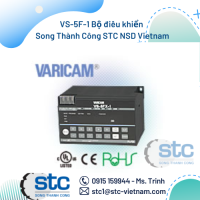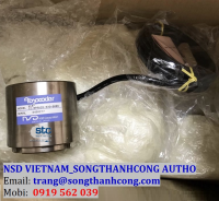


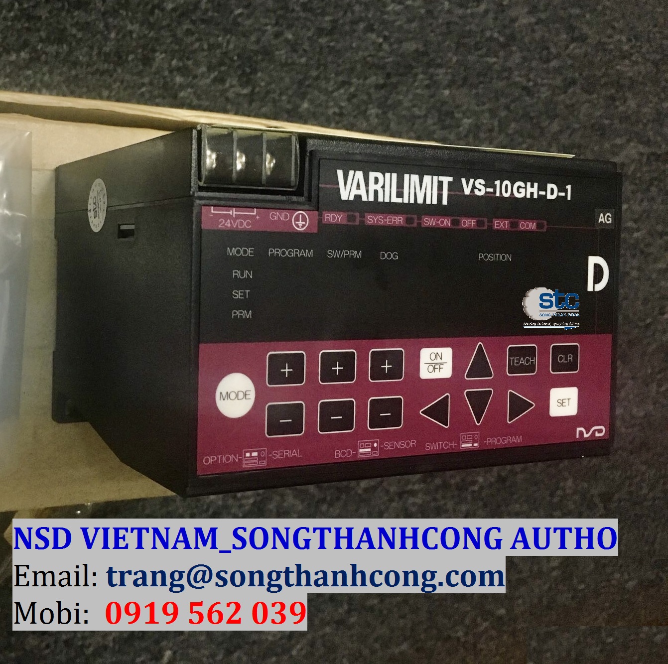
VARILIMIT- Công tắc ngõ ra điều khiển vị trí
Xuất sứ: Japan
Nhà cung cấp: NSD Corp - Đại Lý Song Thành Công
Hãng sản xuất: NSD Corp
Ứng dụng sản phẩm: Ngành Bánh Kẹo, Ngành Dệt, Ngành Thép, Ngành Thực Phẩm, Ngành Xi Măng
NSD GROUP - Sản Phẩm Được Phân Phối Độc Quyền Bởi
SONG THÀNH CÔNG
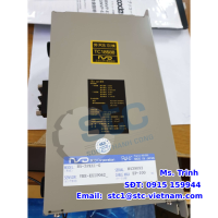
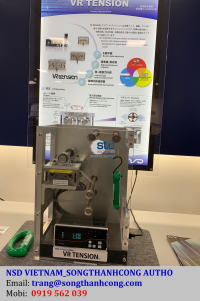
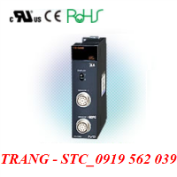
Limit Switch Output Controller VARILIMIT®
Mô tả
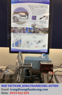
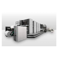
Công tắc điện điều khiển xuất tín hiệu ngõ để ra điều khiển vị trí của hãng NSD được gọi là VARILIMIT là một trong những bộ điều khiển nổi tiếng nhất thiết lập lại giải pháp công tắc giới hạn hành trình. Công tắc hành trình, chúng được sử dụng để điều khiển vị trí, cũng như khóa an toàn, hoặc là đếm số vật thể đi qua một điểm. Công tắc hành trình là một thiết bị cơ điện bao gồm 1 bộ actuator cơ liên kết với bộ tiếp điểm. Khi vật thể đi qua tiếp xúc với actuator, thì thiết bị sẽ hoạt động tạo ra tín hiệu hoặc ngắt kết nối điện. Công tắc hành trình được sử dụng đa dạng trong nhiều ứng dụng và nhiều môi trường bởi sự bên bỉ, dễ cài đặt. Tuy nhiên, công tắc hành trình này sử dụng tiếp xúc cơ học để phát hiện vật thể hoặc vị trí của nó đang di chuyển nên tiếp xúc cơ này lâu dài làm hao mòn vật thể. Vì thế, người vận hành cần bảo trì công tắc cơ này duới sự ảnh hưởng của môi trường.
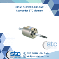
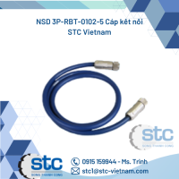
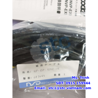
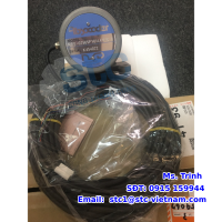
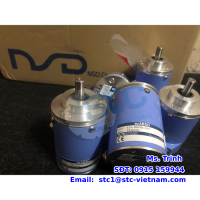
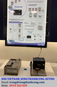
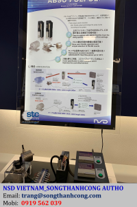
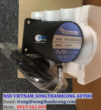
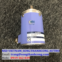
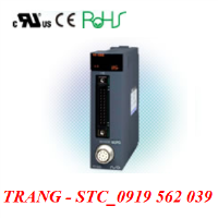
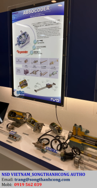
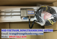
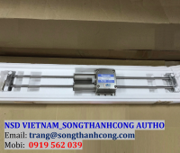
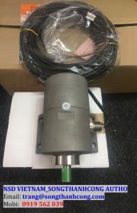
VARILIMIT với ABSOCODER là giải pháp tốt nhất thay thế cho các công tắc hành trình hiện tại. ABSOCODER lắp đặt ở phần cơ khí, và VARILIMIT được lắp đặt ở phòng điều khiển, và chúng được kết nối với nhau qua cáp kết nối.
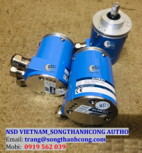
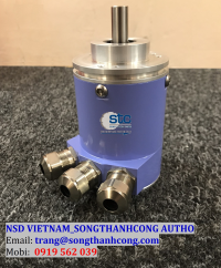
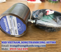
VARILIMIT là kết nối với cảm biến vòng quay tuyệt đối nhiều vòng (MRE series) và ABSOCODER tuyến tính đo vị trí chính xác tuyệt đối, điều khiển tín hiệu ngõ ra và điều khiển giám sát của hệ thống.
Description
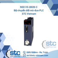
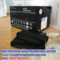
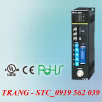
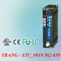
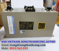
VS-10G Series
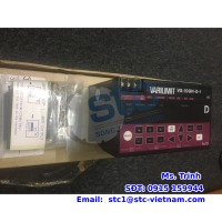
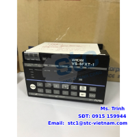
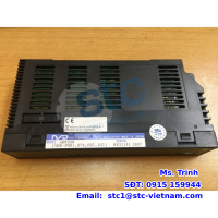
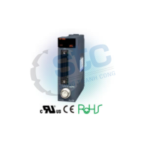
VS-10G
VS-10G is the multi functional smart VARILIMIT with various output options such as digital signal output, analog signal output, motion control and multi preset function.
ADVANTAGE
- Max.30 points of limit switches output
- Max.4 points of motion control On/Off signal can be selected by 1 switch
- Max.1ms of signal updating cycle
- User friendly digital function setting and display
Model coding
VS-10G [1]-[2]-[3]-[4]
[1]Output system
| Code | Specification |
|---|---|
| Blank | Sink type |
[2]Output
| Code | Specification |
|---|---|
| Blank | Switch output only |
| D | Switch output with current position output |
| A | Switch output with position/speed voltage output |
| C | Switch output with position/speed current output |
[3]Điện áp cấp vào
| Code | Specification |
|---|---|
| 1 | 24VDC |
[4]Đặc tính riêng phù hợp cho từng loại cảm biến
| Code | Applicable sensor |
|---|---|
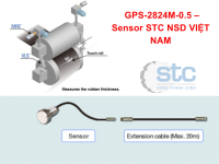
| MP | MRE-32SP062 /MRE-G□SP062 (□ : 64/128/160/256/320) |
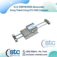
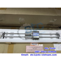
| L | VLS-256PWB/VLS-512PWB /VLS-1024PW |
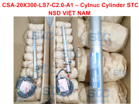
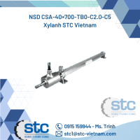
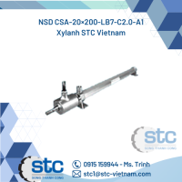
| LC | CSA Cylinder |
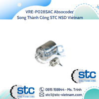
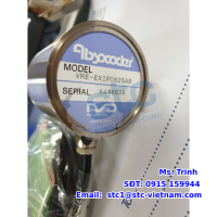
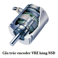
| V2 | VRE-16TS062 |
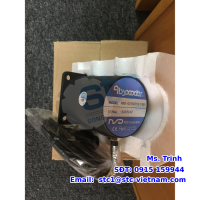
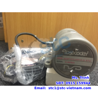
Sơ đồ kết nối ABSOCODER

Specification
General specification
| Item | Specification |
|---|---|
| Converter model | VS-10G-1, VS-10G-D-1, VS-10G-A-1, VS-10G-C-1 |
| Power supply voltage | 24VDC |
| Permissible power voltage range |
21.6 ~ 30VDC |
| Power consumption | 10W or less |
| Insulation resistance | 20MΩ or more between external AC power terminals and ground (by 500 VDC insulation resistance tester) |
| Withstand voltage | 500 VAC, 60Hz for 1 minute between external DC power terminals and ground |
| Vibration resistance | 20m/s2 10 ~ 500Hz, 10cycles of 5 minutes in 3 directions, conforms to JIS C 0040 standard |
| Ambient operating temperature |
0 ~ +55℃ (No freezing) (Surrounding air temperature rating of 55℃ maximum) |
| Ambient operating humidity |
20 ~ 95 %RH (No condensation) |
| Ambient operating environment |
Free from corrosive gases and excessive dust |
| Ambient storage temperature |
-25 ~ +70℃ |
| Grounding | Must be securely grounded (ground resistance of 100 ohm or less) |
| Construction | Inside control panel |
| Mounting | Select from two-screw mounting/DIN rail installation/ on-panel mounting using panel mounting fixture VS-K-F. |
| Outside dimension (mm) | 130(W)×81(H)×99(D) |
| Mass | Approx. 0.7kg |
Performance Specification
| Item | Specification |
|---|---|
| Converter model | VS-10G-1, VS-10G-D-1, VS-10G-A-1, VS-10G-C-1 |
| Number of programs | VS-10B mode:8(1-8) Extended mode:8(1-8) or 32(0-31) |
| Number of switches | 30 |
| Number of multi-dogs | 10 times for each switch output (1-A)(In the case of selecting the VS-10B mode and 8-program in the extended mode) 4 times for each switch output (1-4)(In the case of selecting 32-program in the extended mode) |
| Position data sampling time |
1ms |
| Switch output setting method |
Numerical setting from the panel or teaching |
| Min. setting units | Min. : 0.00001 |
| Position setting range | -999999 ~ 999999 |
| Setting value memory | Non-volatile memories (FRAM) |
| Error detection | Sensor power supply error, Sensor data error, Sensor error, Memory error, No setting error, Preset error, Program No. input error, Multi-dog setting error, System error |
| Communication function | Serial(RS-232C) communication (setting value saving or loading, monitoring, operation commands)
|
Auxiliary function lists
| Item | |||||||||
|---|---|---|---|---|---|---|---|---|---|
| Converter model | VS-10G-1 | VS-10G-D-1 | VS-10G-A-1 | VS-10G-C-1 | |||||
| Operation mode | VS-10B mode |
Extended mode |
VS-10B mode |
Extended mode |
VS-10B mode |
Extended mode |
VS-10B mode |
Extended mode |
|
| Existing Functions |
Protected switch | ✓ | ✓ | ✓ | ✓ | ✓ | ✓ | ✓ | ✓ |
| TEACH setting | ✓ | ✓ | ✓ | ✓ | ✓ | ✓ | ✓ | ✓ | |
| Current position output | - | - | 6-digit BCD/ 24-bit binary |
- | - | - | - | ||
| Current position preset by travel direction input |
✓ | - | ✓ | - | ✓ | - | ✓ | - | |
| Analog voltage output for position |
- | - | - | - | ✓ | ✓ | - | - | |
| Analog current output for position |
- | - | - | - | - | - | ✓ | ✓ | |
| New Functions |
Current position preset by auto-detecting travel direction |
- | ✓ | - | ✓ | - | ✓ | - | ✓ |
| Analog voltage output for speed |
- | - | - | - | - | ✓ | - | - | |
| Analog current output for speed |
- | - | - | - | - | - | - | ✓ | |
| Output HOLD | - | ✓ | - | ✓ | - | ✓ | - | ✓ | |
| Measuring | - | ✓ | - | ✓ | - | ✓ | - | ✓ | |
| Motion recording | - | ✓ | - | ✓ | - | ✓ | - | ✓ | |
| Motion detection | - | ✓ | - | ✓ | - | ✓ | - | ✓ | |
| Sensor filter | - | ✓ | - | ✓ | - | ✓ | - | ✓ | |
| Hysteresis | - | ✓ | - | ✓ | - | ✓ | - | ✓ | |
| Switch output enabling | - | ✓ | - | ✓ | - | ✓ | - | ✓ | |
| External error cancel input | ✓ | ✓ | ✓ | ✓ | ✓ | ✓ | ✓ | ✓ | |
| Multi-origin | - | ✓ | - | ✓ | - | ✓ | - | ✓ | |
| Limitswitchless preset *1 | - | ✓ | - | ✓ | - | ✓ | - | ✓ | |
| Preset error absorption *1 | - | ✓ | - | ✓ | - | ✓ | - | ✓ | |
| Limitswitch timer | - | ✓ | - | ✓ | - | ✓ | - | ✓ | |
| Password | ✓ | ✓ | ✓ | ✓ | ✓ | ✓ | ✓ | ✓ | |
*1 : The function cannot use when connecting to the VRE single-turn type ABSOCODER.
Number of divisions, resolution, and sensor cable length of the ABSOCODER sensor
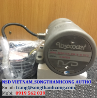
MRE Multi-turn type
| Item | Specification | ||||||
|---|---|---|---|---|---|---|---|
| Sensor model | MRE-32SP062 | MRE-G□SP062 □ : Total number of turn | |||||
| Total number of turns | 32 | 64 | 128 | 160 | 256 | 320 | |
| Divisions/Turn | 4096 | 2048 | 1024 | 819.2 | 512 | 409.6 | |
| Total number of divisions | 131072 | ||||||
| Position detection format | Absolute position detection | ||||||
| Max. sensor cable length |
Standard | 100m | 100m | ||||
| Robotic(RBT) | 40m | 70m | |||||
VLS Linear type Absolute & dual-rod type
| Item | Specification | |||
|---|---|---|---|---|
| Sensor model | VLS-256PWB | VLS-512PWB | VLS-1024PW | |
| Absolute detection range |
256mm | 512mm | 1024mm | |
| Resolution | 0.00391mm | 0.00781mm | 0.0156mm | |
| Total number of divisions | 65536 | |||
| Position detection format | Absolute position detection | |||
| Max. sensor cable length |
Standard | 100m | ||
| Robotic(RBT) | 50m | |||
CYLNUC
| Item | Specification | |
|---|---|---|
| Sensor model | CSA | |
| Absolute detection range |
12.8mm | |
| Resolution | 0.00156mm | |
| Position detection format | Semi - absolute position detection | |
| Max. sensor cable length |
Standard | 100m |
| Robotic(RBT) | 50m | |
VRE Single-turn type (High-resolution)
| Item | Specification | |
|---|---|---|
| Sensor model | VRE-16TS062 | |
| Total number of turns | 1 | |
| Number of divisions | 65536 | |
| Position detection format | Absolute position detection | |
| Max. sensor cable length |
Robotic(RBT) | 100m |
I/O spcification
| Item | VS-10G-1 | VS-10G-D-1 | VS-10G-A-1 | VS-10G-C-1 | Description | |
|---|---|---|---|---|---|---|
| Input Signals |
Program No. | 8 points | 8 points | 8 points | 8 points | Inputs the exteral program No. |
| Current position preset | 3 points | 3 points | 3 points | 3 points |
The current position value is changed to a value which is pre-designated by the external signal. |
|
| External measuring trigger |
1 point | 1 point | 1 point | 1 point |
When this signal is input from the host controller, the Current Position Value will be held so that it can be read as a measuring value. |
|
| Switch output enabling | 1 point | 1 point | 1 point | 1 point | The switch signal is output when turning ON this signal. | |
| DTC input for BCD output |
- | 1 point | - | - |
Updating of the current position output will be suspended while this signal turns ON. |
|
| Error cancel | 1 point | 1 point | 1 point | 1 point | Cancels an error when this input is turned ON. | |
| Output signals |
Switch outputs*2 | 30 points | 30 points | 30 points | 30 points | ON/OFF signal will be output based on the switch output setting values. |
| System ready | 1 point | 1 point | 1 point | 1 point | Outputs when controller and sensor are functioning normally. | |
| Program No. | 8 points | 8 points | 8 points | 8 points | The currently selected program No. is output. | |
| Current position value (BCD/binary) |
- | 24 points (6-digit BCD/ 23-bit binary+sign) |
- | - | Outputs current position or measuring values in BCD or binary code. | |
| Decimal point | - | 3 points | - | - | Outputs current position or measuring values in BCD or binary code. | |
| BCD minus sign | - | 1 point | - | - | Outputs when negative current position or measuring values are output in BCD code. | |
| Latch pulse | - | 1 point | - | - | This is updating timing signal of the current position outputs. | |
| HOLD measuring completed *2 |
1 point | 1 point | 1 point | 1 point |
Turns ON when the HOLD measuring is completed and this current position value is held. |
|
| Motion detection *3 | 1 point | 1 point | 1 point | 1 point | Outputs when the detected travel direction and speed match the predetermined values. | |
| Preset error *4 | 1 point | 1 point | 1 point | 1 point |
Outputs when the current position preset signal is turned on in the position outside of the preset possible range. |
|
*2 : It is assigned to the switch output 28 when using the HOLD measuring completed signal.
*3 : It is assigned to the switch output 29 when using the motion detection signal.
*4 : It is assigned to the switch output 30 when using the preset error signal.
Switch output and program No. connector
| Item | Input specifications | Item | Output Specifications | |||
|---|---|---|---|---|---|---|
| Input signals | Program No. Current position preset External measuring trigger Switch output enabling Error cancel |
Output signals | Program No. Switch output System ready HOLD measuring completed Motion detection Preset error |
|||
| Input circuit | DC input, photo-coupler isolation | Output circuit | photo - coupler isolation | |||
| Rated input voltage | 12VDC | 24VDC | Rated load voltage | 12/24VDC | ||
| Rated input current | 4mA | 10mA(24VDC) | Load voltage range | 10.2 ~ 30VDC | ||
| Input voltage range | 10.2 ~ 30VDC | Max. load current | 100mA | |||
| ON voltage | 10VDC or more | Current leak when OFF |
0.1mA or less | |||
| OFF voltage | 4VDC or less | Max. voltage drop when ON |
2.0V or less (at 100mA) | |||
| Response time |
OFF to ON | 0.04 ms (at 24V input voltage) | Response time |
OFF to ON | 1 ms (at 100mA load-current resistance load) | |
| ON to OFF | 0.2ms (at 24V input voltage) | ON to OFF | 1 ms (at 100mA load-current resistance load) | |||
BCD output connector
| Item | Input specifications | Item | Output Specifications | |||
|---|---|---|---|---|---|---|
| Input signals | DTC input for BCD output | Output signals | Current position value (BCD / binary) Decimal point BCD minus sign Latch pulse |
|||
| Input circuit | DC input, photo-coupler isolation | Output circuit | Transistor (open-collector)output, photo-coupler isolation | |||
| Rated input voltage | 12VDC | 24VDC | Rated load voltage | 12/24VDC | ||
| Rated input current | 4mA | 10mA | Load voltage range | 10.2 ~ 30VDC | ||
| Input voltage range | 10.2 ~ 30VDC | Max. load current | 20mA 100mA(latch pulse only) |
|||
| ON voltage | 10VDC or more | Current leak when OFF |
0.1mA or less | |||
| OFF voltage | 4VDC or less | Max. voltage drop when ON |
1.5V or less (at 20mA) 1.5V or less (at 100mA)(latch pulse only) |
|||
| Response time |
OFF to ON | 0.04 ms (at 24V input voltage) | Response time |
OFF to ON | 1 ms (at 100mA load-current resistance load) | |
| ON to OFF | 0.2ms (at 24V input voltage) | ON to OFF | 1 ms (at 100mA load-current resistance load) | |||
Analog output connector
Position/Speed Voltage Output
| Item | Specification |
|---|---|
| Output voltage | VS-10B Mode: 0 ~ 10VDC or −10 ~ +10VDC Extended mode: −10 ~ +10VDC Position/Speed and voltage can be set as required at the parameter. |
| External load resistance | 1kΩ to 1MΩ |
| Output voltage resolution | 0.3051 mV (−10V to +10V / 65536 divisions) |
| Output voltage accuracy | 100mV(0 ~ +55℃) |
| Analog response time | Max. 100µs (Switching between 10V and 0V) |
| Sampling time | 1ms |
| Isolation format | Insulated between control and output circuits |
Position/Speed Current Output
| Item | Specification |
|---|---|
| Output current | 4 ~ 20mADC Position/Speed data for 4mADC and Position/Speed data for 20mADC can be set as required at the parameter. |
| External load resistance | 510Ω or less |
| Output current resolution | 0.24µA (4mA to 20mA / 65536 divisions) |
| Output current accuracy | 200µA(0 ~ +55℃) |
| Analog response time | Max. 100µs (Switching between 20mA and 4mA) |
| Sampling time | 1ms |
| Isolation format | Insulated between control and output circuits |