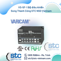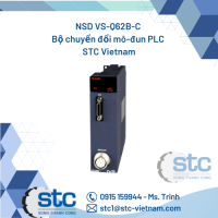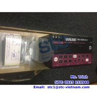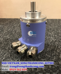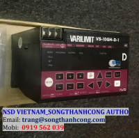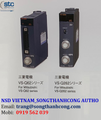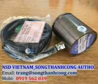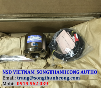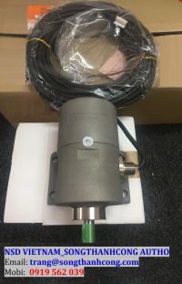


VARICAM - Công tắc "Cam" điện từ điều khiển tín hiệu ngõ ra
Xuất sứ: Japan
Nhà cung cấp: NSD Group
Hãng sản xuất: NSD Corp
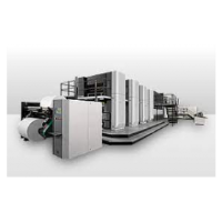
Ứng dụng sản phẩm: Ngành Bánh Kẹo, Ngành Dệt, Ngành Gỗ, Ngành Thép, Ngành Thực Phẩm, Ngành Xi Măng
NSD GROUP - Sản Phẩm Được Phân Phối Độc Quyền Bởi
SONG THÀNH CÔNG
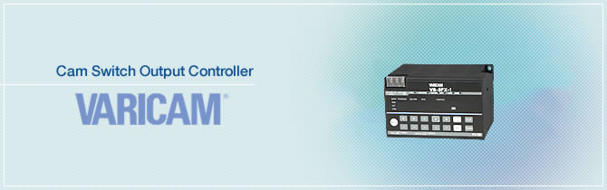
VARICAM® - Công tắc "Cam" điện từ điều khiển tín hiệu ngõ ra
Công tắc "Cam" điện từ điều khiển xuất tín hiệu ngõ để ra điều khiển của hãng NSD được gọi là VARICAM là một trong những bộ điều khiển nổi tiếng nhất thiết lập lại giải pháp công tắc "Cam" loại cơ truyền thống. Công tắc giới hạn "Cam" được sử dụng để chuyển đổi chuyển động cơ thành tín hiệu điều khiển điện để điều khiển tự động vị trí và giới hạn kết thúc hành trình về mặt cơ khí của actuator. Đây là loại công tắc hành trình truyền thống sử dụng tiếp xúc vật lý để phát hiện sự hiện diện của vật thể, vì thế, người vận hành cần cài đặt và bảo trì phần cơ khí.
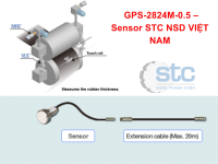
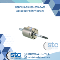
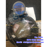
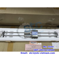
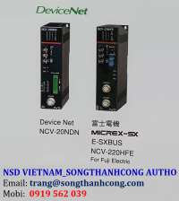
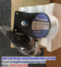
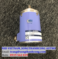
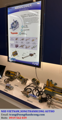
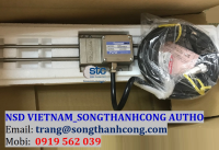
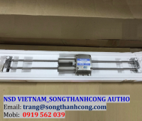
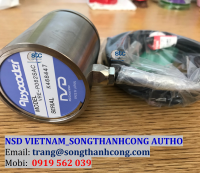
VARICAM với ABSOCODER là giải pháp tốt nhất thay thế cho các công tắc hành trình "Cam" hiện tại. ABSOCODER lắp đặt ở phần cơ khí, và VARICAM được lắp đặt ở phòng điều khiển, và chúng được kết nối với nhau qua cáp kết nối.
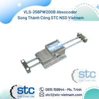
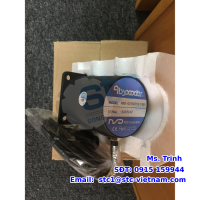
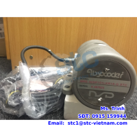
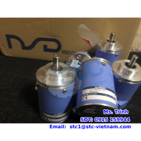
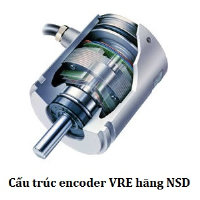
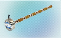
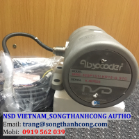
VARICAM thì luôn luôn kết nối với cảm biến vòng quay tuyệt đối 1 vòng (VRE series) đo được góc 360° và công tắc ngõ ra On/Off với sự lựa chọn tín hiệu và các chức năng điều khiển của hệ thống.
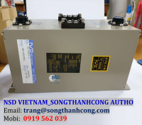
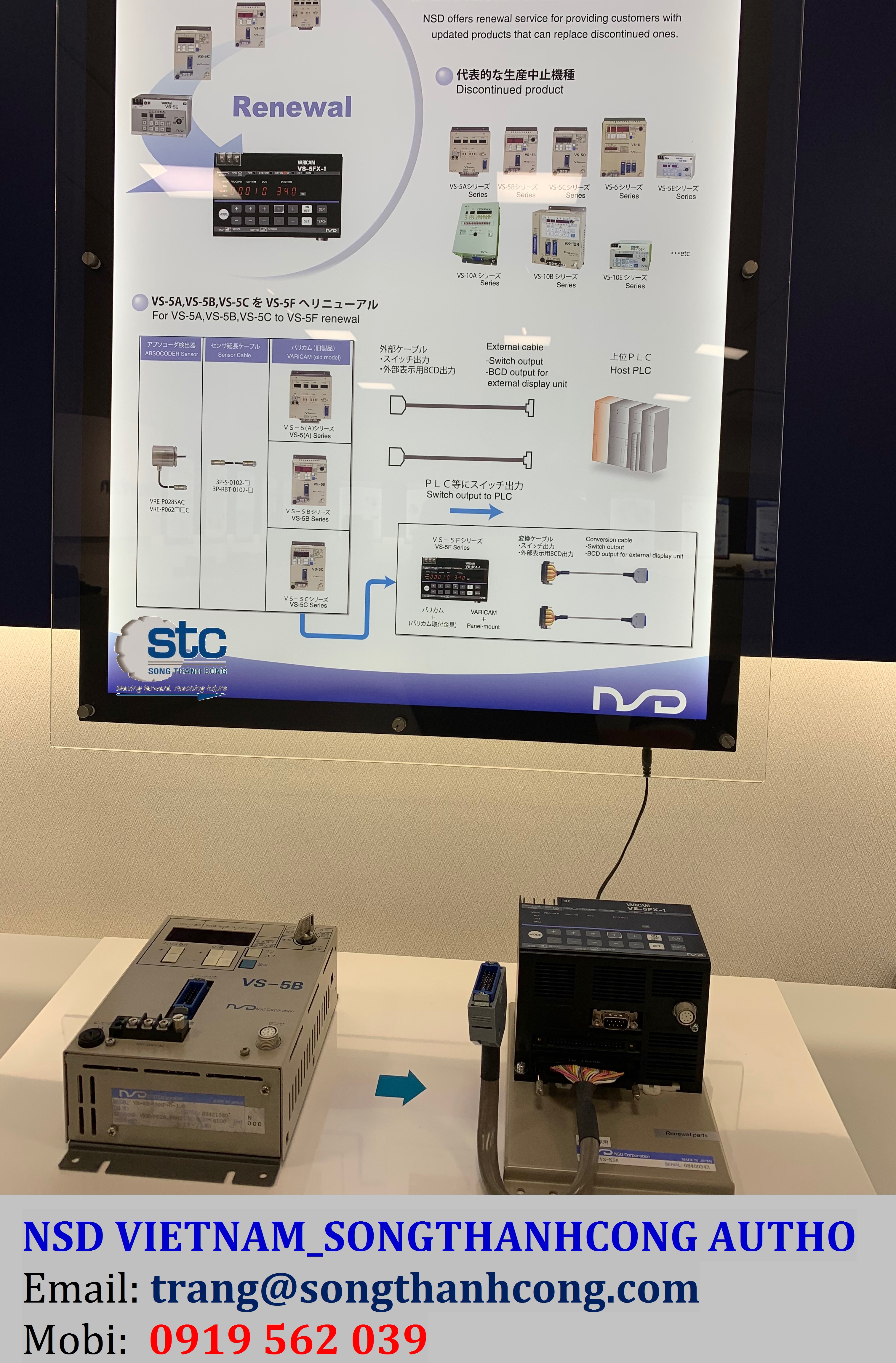
Mô tả
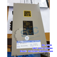
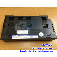
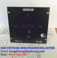
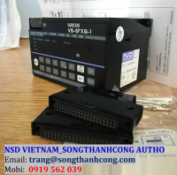
VS-5F: là dòng VARICAM tiêu chuẩn với công tắc ngõ ra "cam"
Ưu điểm
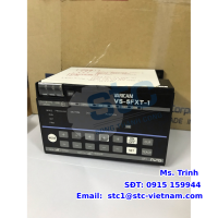
- Cấu hình tiêu chuẩn công tắc với 24 tiếp điểm on/off cho tín hiệu ngõ ra (Dòng VS-5FX tối đa 40 tiếp điểm)
- Lựa chọn và điều khiển on/off theo góc 0.5°
- Có thể chọn tối đa 10 tiếp điểm của góc công tắc cam bằng 1 công tắc tín hiệu
- Tối đa 0.176ms cho mỗi chu kì cập nhật tín hiệu (Khi dãy đo ON/OFF là cho mỗi lần 1°)
- Sử dụng thân thiện với chức năng cài đặt tín hiệu số và màn hình hiển thị.
Model coding
VS-5F[1][2]-[3]
[1]No. of programs×No. of switch outputs, and others
| Code | Output code |
|---|---|
| Blank | 1 program×24 switches |
| D | 8 programs×24 switches, current position BCD output. |
| X | 16 programs×40 switches or 32 programs×24 switches, current position BCD output. |
[2]Output system
| Code | Output system |
|---|---|
| Blank | Sink type |
[3]Power supply voltage
| Code | Specification |
|---|---|
| 1 | 24VDC |
ABSOCODER Basic Configuration

Đặc tính
Đặc tính chung
| Item | Specification | |||||
|---|---|---|---|---|---|---|
| Converter model | VS-5F-1 | VS-5FD-1 | VS-5FX-1 | |||
| Power supply voltage | 24VDC | |||||
| Permissible power voltage range |
21.6 ~ 30VDC | |||||
| Power consumption | 10W or less | |||||
| Insulation resistance | 20MΩ or more between external AC power terminals and ground (by 500 VDC insulation resistance tester) |
|||||
| Withstand voltage | 500 VAC, 60Hz for 1 minute between external DC power terminals and ground |
|||||
| Vibration resistance | 20m/s2 10 ~ 500Hz, 10cycles of 5 minutes in 3 directions, conforms to JIS C 0040 standard |
|||||
| Ambient operating temperature |
0 ~ +55℃ (No freezing) (Surrounding air temperature rating of 55℃ maximum) |
|||||
| Ambient operating humidity |
20 ~ 90 %RH (No condensation) | |||||
| Ambient operating environment |
Free from corrosive gases and excessive dust | |||||
| Ambient storage temperature |
-10 ~ +70℃ | |||||
| Grounding | Must be securely grounded (ground resistance of 100 ohm or less) | |||||
| Construction | Inside control panel | |||||
| Mounting | Select from two-screw mounting/DIN rail installation/ on-panel mounting using panel mounting fixture VS-K-F. |
|||||
| Outside dimension (mm) | 130(W)×81(H)×99(D) | |||||
| Mass | Approx. 0.7kg | |||||
Đặc tính hiệu suất
| Item | Specification | |||||
|---|---|---|---|---|---|---|
| Converter model | VS-5F-1 | VS-5FD-1 | VS-5FX-1 | |||
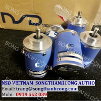
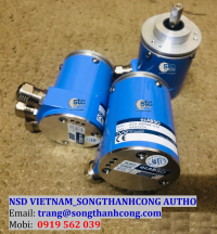
| Applicable sensor | VRE-P028,VRE-P062 | |||||
| Min. setting units | 0.5° | |||||
| Number of programs (Panel display) | 1 | 8(0 ~ 7) | 16 (0 ~ 15) |
32 (0 ~ 31) |
||
| Number of switch outputs | 24 | 24 | 40 | 24 | ||
| Number of multi-dogs | 10 times for each switch output (0 ~ 9) | |||||
| Position data sampling time (permissible speed) |
0.176ms (900 r/min When ON / OFF range is 1 degree) | |||||
| Switch output setting method | Numerical setting from the panel or teaching | |||||
| Setting value memory | Non-volatile memories (FRAM) | |||||
| Error detection | Sensor power error, Sensor error , Memory error , No setting error , Setting impossible error , System error | |||||
| Auxiliary functions | Protected switch | ✓ | ✓ | ✓ | ||
| Setting change during operation |
✓ | ✓ | ✓ | |||
| Current position value (BCD, gray code (720-division)) |
- | ✓ | ✓ | |||
| Binary speed output | - | Selectable between current position output and speed output | Selectable between current position output and speed output | |||
| Timing pulse output | ✓ | ✓ | ✓ | |||
| Motion detection switch | Selectable between timing pulse and speed detection output | Selectable between timing pulse and speed detection output | Selectable between timing pulse and speed detection output | |||
| Switch output enable | ✓ | ✓ | ✓ | |||
| Hysteresis | ✓ | ✓ | ✓ | |||
| Exterminal origin set | - | - | ✓ | |||
| Arbitrary pulse output | ✓ | ✓ | ✓ | |||
| Current position HOLD | - | ✓ | ✓ | |||
| Error cancel | ✓ | ✓ | ✓ | |||
| Password | ✓ | ✓ | ✓ | |||
| Communication function |
Serial (RS-232C) communication (setting value saving or loading, monitoring, operation commands)
|
|||||
| Connection of an external display unit |
I/O connection | - | ✓ | ✓ | ||
| Communication connection |
✓ | ✓ | ✓ | |||
| Max. sensor cable length |
Standard | 100m | ||||
| Robotic(RBT) | 100m | |||||
Đặc tính I/O
| Item | VS-5F-1 | VS-5FD-1 | VS-5FX-1 | Description | |
|---|---|---|---|---|---|
| Input signals |
Program No. | - | 3 points | 4/5 points | Inputs the exteral program No. |
| Current position HOLD | - | 1 point | - | Used to prevent the current position value from changing when controller reading occurs. | |
| Current position HOLD or external origin set |
- | - | 1 point | Input to prevent current position from changing or for origin setting. | |
| Error cancel | 1 point | 1 point | 1 point | Input to cancel an error display. | |
| Switch output enable | 1 point | 1 point | 1 point | Switch signal will be output only upon the input of this signal. | |
| Output signals |
Switch output / Arbitrary pulse output |
24 points | 24 points | 40/24 points | ON/OFF signal will be output based on the switch setting value, or pulse signal will be output based on equally dividing a single rotation (division selectable from 1 ~ 360). |
| Timing pulse / Motion detection switch |
1 point | 2 points | 1 point | 60, 180 or 360 pulse signals will be output per rotation, or ON/OFF signal will be output based on the speed setting value. | |
| System ready | 1 point | 1 point | 1 point | Outputs when controller and sensor are functioning normally. | |
| Program No. | - | 3 points | 4/5 points | The currently selected Program No. is output. | |
| Current position value (BCD, gray code (720-division)) / Speed Binary output |
- | 11 points | 11 points | Current position (3-digit BCD + 0.5-deg display) signal will be output, or rotational speed will be output in binary code. | |
| Latch pulse | - | 1 point | 1 point | Outputs a timing signal which ensures that the current position is read in a stable condition. | |
| Item | Input specifications | Item | Output Specifications | ||
|---|---|---|---|---|---|
| Input signals | Program No. External origin set Current position HOLD Error cancel Switch output enable |
Output signals | Switch output or arbitrary pulse Program No. Sysytem ready |
Motion detection switch or timing pulse |
Current position value (BCD, g ray code (720-division)) or speed (binary) |
| Input circuit | DC input, photo-coupler isolation | Output circuit | Transistor (open-collector), photo-coupler isolation | ||
| Input logic | Negative logic | Output logic | Negative logic | Negative logic | Positive logic*1 |
| Rated input voltage | 24VDC | Rated load voltage | 24VDC(30VDC max.) | ||
| Rated input current | 10mA(24VDC) | Max. load current | 100mA | 100mA | 10mA(24VDC) |
| ON voltage | 10VDC or more | Max. voltage drop when ON |
2.0V | 1.5V | 0.7V |
| OFF voltage | 4 VDC or less | ||||